The OSI (Open Systems Interconnection) model is the common language of networking. Whether you are troubleshooting a dead cable or configuring a complex router, you operate within one of these seven layers.
Additionally, For the CompTIA Network+ OSI model, memorizing these layers and understanding how data flows through them is essential.
The Mnemonic to Remember
All People Seem To Need Data Processing (Application, Presentation, Session, Transport, Network, Data Link, Physical)
The 7 Layers Explained
| Layer | Name | Function | Key Components/Protocols |
| 7 | Application | User interface and network services | HTTP, HTTPS, FTP, DNS, SMTP |
| 6 | Presentation | Data formatting, encryption, compression | SSL/TLS, JPEG, MP4, ASCII |
| 5 | Session | Establishes/manages/ends connections | RPC, NetBIOS, Sockets |
| 4 | Transport | End-to-end communication, reliability | TCP, UDP, Port Numbers |
| 3 | Network | Logical addressing and routing | IP addresses, Routers, Packets |
| 2 | Data Link | Node-to-node transfer, MAC addressing | MAC addresses, Switches, Frames |
| 1 | Physical | Transmits raw bits over media | Cables (Cat6), Hubs, Fiber, Bits |
How Data Travels: The Encapsulation Process
When you send an email, data starts at Layer 7 and moves down through the stack. Each layer adds a specific header containing control information. This process is called Encapsulation. When the receiving device gets the data, it performs the reverse process, known as Decapsulation.
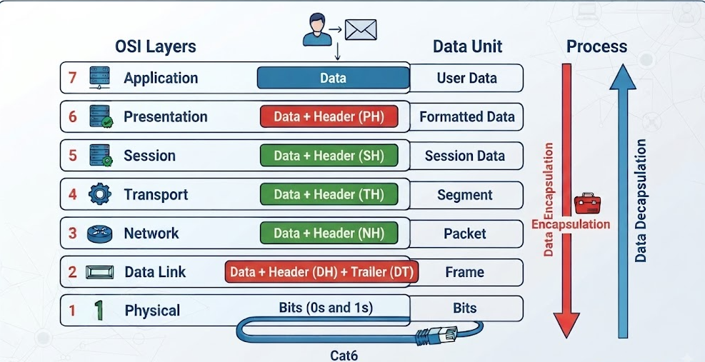
As illustrated in the diagram above:
- Layer 4 (Transport): The data is broken into Segments (TCP) or Datagrams (UDP). Port numbers are added here.
- Layer 3 (Network): Segments are wrapped into Packets. Logical IP addresses are added.
- Layer 2 (Data Link): Packets are wrapped into Frames. Physical MAC addresses are added for local delivery.
- Layer 1 (Physical): Everything is converted into Bits (1s and 0s) and transmitted across physical media.
Troubleshooting Tip for the Exam
When you encounter a question on the CompTIA Network+ OSI model about where to start troubleshooting, follow the Bottom-Up approach.
By starting at the lower layers, you verify components before moving up.
- Is the physical link active? Check the cable/lights (Layer 1).
- Does the device have a MAC address? (Layer 2).
- Can the device ping its gateway? (Layer 3).
Master the OSI Model & Network+
- 🚀 Boost your prep: Get instant access to my CompTIA Network+ 6 Full Mock Exams.
- 📚 Recommended Reading: Keep the CompTIA Network+ N10-008 Cert Guide by Anthony Sequeira on your desk.
- 📺 Visual Learning: Subscribe to my YouTube channel for deep-dive tutorials.